Unified Modeling Language (UML) is a light of accuracy and clarity in the huge field of software development. In addition to providing a comprehensive toolbox of carefully produced diagrams to assist system and software engineers at every level of the development lifecycle, UML serves as a standard modeling language.
UML is more than just a tool; it’s a set of best engineering practices developed over time and specially designed to deal with the complexity of contemporary software systems. When it comes to creating and presenting software artifacts and defining and illustrating system architectures, UML offers developers a strong foundation that helps them express their concepts clearly and precisely.
Fundamentally, UML facilitates efficient communication across project teams, allowing stakeholders to investigate possible designs, confirm architectural choices, and coordinate their activities in the direction of a shared objective. UML breaks down language barriers and promotes smooth cooperation across a variety of teams and disciplines by primarily using graphical notations.
We set out to discover the fundamentals of UML throughout this piece. We explore its history, following its developmental trajectory that has molded it into a key component of object-oriented software programming. We also take a thorough look at every kind of UML diagram, providing in-depth analysis and useful examples to shed light on their function and real-world applications.
Come along as we break down the mystery surrounding UML and see how it can revolutionize the way we plan, create, and maintain software systems. UML continues to be a monument to the strength of visual modeling in influencing the direction of technology, from its modest origins to its essential position in contemporary software development.
Understanding UML
A standardized modeling language called Unified Modeling Language (UML) is used in software engineering to describe, build, visualize, and record the artifacts of an object-oriented programming (OOP) system. It offers a collection of graphical notations that may be used to depict the relationships, behavior, and structure of software systems.

The purpose of UML is to combine the greatest features of earlier notations into a single standard notation that can be utilized by all object-oriented techniques. Numerous applications are possible using UML because of its design. Because of this, it offers frameworks for a wide variety of systems and tasks (such as distributed systems, analysis, system design, and deployment).
The unification of OMT produced the notation known as UML.
- Method of Object Modeling The optimal method for analysis and data-intensive information systems was OMT [James Rumbaugh, 1991].
- Booch [Grady Booch, 1994] – outstanding in terms of conception and execution. Grady Booch was a key contributor to the creation of object-oriented methods for the Ada language and had worked with it extensively. Despite the strength of the Booch technique, the notation was not well welcomed (his models were dominated by several cloud forms, which were not particularly neat).
- Use Cases are a paradigm that was part of OOSE (Object-Oriented Software Engineering [Ivar Jacobson 1992]). Use Cases are an effective method for comprehending a system’s overall behavior, an area in which OO has historically lagged.
The OMT founder, Jim Rumbaugh, surprised the software community in 1994 when he joined Grady Booch at Rational Corp. after leaving General Electric. The partnership’s goal was to combine their concepts into a single, cohesive approach; in fact, the method’s working title was the “Unified Method”
When OOSE’s inventor, Ivar Jacobson, joined Rational in 1995, his ideas—especially the notion of “Use Cases”—were incorporated into the newly developed Unified Method, which is currently known as the Unified Modelling Language1. The trio of Rumbaugh, Booch, and Jacobson is referred to as the “Three Amigos” with love.
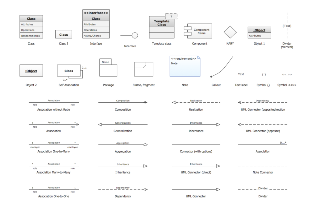
UML model elements
An abstraction of a structural or behavioral aspect of the system you are modeling, a UML model element gives a model semantic substance.
Model elements show up beneath the model or the model element they belong to in the Project Explorer view. To offer information about the system and to make the model simpler to comprehend, you may add, change, sort, group, and filter model elements.
Every model element has attributes, such as a name. Certain UML model elements can be further defined by additional features, such as actions and properties that are part of the class.
- Structural model elements: These components represent the fixed components of a system. Classifiers like actors, classes, components, information items, and nodes are a few examples.
- Behavioral model elements: These components simulate a system’s dynamic components. Behavioral model components are typically found in the state machine and interaction diagrams. Activities, choices, messages, objects, and states are a few examples.
- Organizational model elements: These components form logical sets out of model constituents. One aspect of an organizational model is a package.
- Annotation model elements: These components offer remarks and explanations. Two types of annotation model components are constraints and Notes.

UML Diagrams for OOP
A vast collection of diagrams for visualizing many elements of object-oriented programming (OOP) systems is provided by the Unified Modeling Language (UML). Developers may depict different aspects of a system’s behavior, design, and structure with the use of UML diagrams, each of which has a distinct function. Let’s examine the OOP UML diagrams that are most frequently used:
- Class diagram: A class diagram is a static view of an application, illustrating objects and relationships within the system. It aids in software development by displaying attributes, classes, functions, and relationships, and is considered a structural diagram due to its collection of classes, interfaces, associations, collaborations, and constraints. Class diagrams are widely used UML diagrams for building static views of applications, describing system responsibilities, serving as a base for component and deployment diagrams, and incorporating forward and reverse engineering.
- Object diagrams: Object diagrams are derived from class diagrams and represent an instance of a class diagram. They represent a static view of a system, rendering a set of objects and their relationships. The purpose of a diagram, like object diagrams, is to capture the static view of a system at a specific moment. They are similar to class diagrams, but represent concrete instances and relationships, allowing for forward and reverse engineering, understanding of system interactions, and practical application.
- Sequence diagram: Sequence diagrams, also known as event diagrams or scenario diagrams, are a type of interaction diagram used by software developers and business professionals to understand requirements for new systems or document existing processes. There are two types: UML diagrams and code-based diagrams, with Lucidchart’s UML diagramming software providing all necessary shapes and features for both.
- Use Case Diagram: A Use Case Diagram is a type of Unified Modeling Language (UML) diagram that represents the interaction between actors and a system to achieve specific goals. It provides a high-level overview of the system’s functionality and is recommended to supplement more descriptive textual use cases. UML is used to build diagrams, with use cases represented by oval shapes, actors represented by stick figures, and system boundaries depicted by boxes.
- State diagram: A state diagram, also known as a Harel state chart or state machine diagram, is a UML diagram that depicts the behavior of a single object in response to a series of system events. It is useful for modeling and visualizing the dynamic behavior of a system, particularly in embedded systems where hardware interacts with software to perform tasks.
- Activity diagram: Activity Diagrams are used to coordinate activities at various abstraction levels, focusing on events, operations, and their relationships in use cases. They are useful for modeling business workflows, identifying candidate use cases, identifying pre-and post-conditions, modeling workflows between/within use cases, and modeling complex operations on objects.

Benefits of UML
Some of the advantages of UML for software engineers are as follows:
- Helps in communication: Software developers may exchange design information using a common language thanks to UML. Because developers won’t need to learn a new, proprietary software language, this saves time and money. It also makes it easier to communicate with other groups or people who are reviewing the design.
- Saves time: UML automates various design processes, which may save developers time. Additionally, by avoiding possible faults in their applications, developers may save time during the development and testing phases by utilizing this language. UML enables developers to reuse code, which can also result in time savings throughout the development process.
- Enhances collaboration: Because UML provides a standard language, software developers from various companies may collaborate on the same project. This facilitates better teamwork and makes the design process go more smoothly. It also aids in the early detection of any issues during the design phase.
- Provides a better understanding of a system: With UML, developers may view a system’s overall architecture. They will be better able to comprehend the system and recognize any possible problems as a result. They may also see the interactions between various system components thanks to it.
- Unifies design: Software and system design may be done in a standard manner with UML. This makes it possible for a more cohesive design process and promotes standard compliance. It also provides more productivity and simpler design evaluations.
Common Pitfalls and How to Avoid Them
Although the Unified Modeling Language (UML) is an effective tool for object-oriented programming (OOP) system visualization, there are several typical mistakes that programmers make when drawing UML diagrams. It is crucial to comprehend these hazards and know how to avoid them to create precise and useful models. Let’s look at some of the most typical problems and how to avoid them:
- Over-Modeling or Under-Modeling: Over-modeling in UML diagrams can overwhelm stakeholders while under-modeling omits important system aspects. To avoid these pitfalls, focus on essential concepts, simplicity, and regular review and refinement to ensure accurate representations of the system’s requirements and design.
- Neglecting Maintenance of UML Diagrams: UML diagrams should evolve with the system they represent, so neglecting to update and maintain them can lead to outdated or inaccurate representations, confusion, and discrepancies between the model and actual implementation. To avoid this, establish a regular maintenance process.
- Misinterpreting Relationships and Dependencies: Misinterpreting relationships and dependencies in UML diagrams can lead to incorrect design decisions and implementation errors. To avoid this, accurately define and represent relationships and dependencies, understand their semantics, and validate diagrams against system requirements and design specifications.
- Lack of Consistency and Standards: Inconsistencies in notation, naming conventions, or modeling practices can hinder the clarity and effectiveness of UML diagrams. To avoid confusion and miscommunication, establish and adhere to clear guidelines, and use templates, and style guides for consistent diagram interpretation.
- Overlooking Stakeholder Feedback: Involving stakeholders in the modeling process from the beginning can prevent models from accurately reflecting their needs or expectations. By using collaborative tools like workshops, reviews, and walkthroughs, stakeholders can actively listen and incorporate their suggestions into the models.
Developers can create UML diagrams effectively communicating object-oriented system design, behavior, and structure, facilitating understanding, collaboration, and decision-making throughout the software development process by addressing common pitfalls.
As we conclude our examination of the Unified Modeling Language (UML), it is evident that UML is a cornerstone of object-oriented programming (OOP). UML gives developers the tools they need to precisely design, represent, and explain large software systems using a wide range of diagrams and standardized notation. Unified Modeling Language (UML) is a fundamental tool in object-oriented programming, providing developers with a clear and precise way to visualize, design, and communicate complex software systems. Its versatility extends to documentation, communication, code generation, and reverse engineering.
UML is a crucial tool for developers, guiding them through software development and modern system complexities. It helps bridge the gap between concept and implementation, enabling developers to create long-lasting software systems. As a versatile and reliable tool, UML ensures developers can confidently embark on their coding journeys.

